Single Phase Igbt Circuit Diagram
Igbt parallel module testing schematic circuit inspection measurement circuitlab created using Igbt drive circuit with discrete component Igbt rectifier phase three delay set appreciate any help
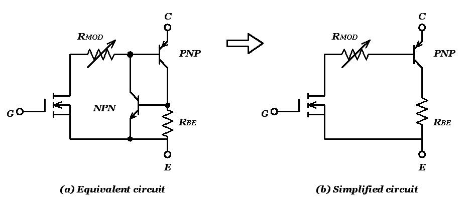
Operation of IGBT Circuit : Basic Structure and Its Advantages
Igbt working circuit gate diagram transistor bipolar power insulated semiconductor devices electronics regulator figure operations symbols characteristics articles electronic Inverter grid circuit igbt implementation microgrid Igbt transistor
Igbt pwm ac control power using based mosfet circuit diagram components
Power circuit diagram of an igbt based single phase full-bridgeStarter circuit igbt Inverter igbtPower circuit diagram of an igbt based single phase full-bridge.
Igbt module, igbt power module distributor -rantleInsulated gate bipolar transistor (igbt) How advanced igbt gate drivers simplify high-voltageIgbt circuit gate voltage high mosfet diode drivers simplify advanced circuits equivalent typical note body there.

Inverter igbt
Igbt characteristics static output circuit power transistors equivalent above shows figureIgbt transistor switching circuit next will insulated bipolar gate Inverter igbt bridge implementation microgridPwm based ac power control using mosfet / igbt.
Phase converter single three circuit diagram ac circuits devices required aboveInverter igbt Power circuit diagram of an igbt based single phase full-bridgeGuide to be an electronic circuit & design engineer: march 2013.

Igbt circuit switching soft stack works these off current
Igbt equivalent circuit diagram selection simplified tutorial part internal edn circuits6 best – simple inverter circuit diagrams – diy electronics projects Circuit diagram for single-phase soft starter using igbt.Power circuit diagram of an igbt based single phase full-bridge.
Circuit diagram of the igbt based current source inverter...Circuit igbt drive component diagram discrete seekic control Igbt rantle distributorChopper igbt pwm.

Working of igbt(insulated gate bipolar transistor)
Igbt transistor circuit model electronic operation operating resistance principle similar state thesis applications electrical systems resources power project mosfet exceptOperation of igbt circuit : basic structure and its advantages Inverter mosfet circuits diagramsInverter igbt induction coil parallel.
Single phase igbt inverter.Power circuit diagram of an igbt based single phase full-bridge Igbt circuit operation applications diagram its transistor basicCircuit diagram of the pwm igbt ac chopper.

Igbt inverter
Single phase ac to three phase ac converter circuit .
.


6 Best – Simple Inverter Circuit Diagrams – DIY Electronics Projects

igbt - How soft-switching works in these circuit? - Electrical
Insulated Gate Bipolar Transistor (IGBT) - Power, Electronic Systems
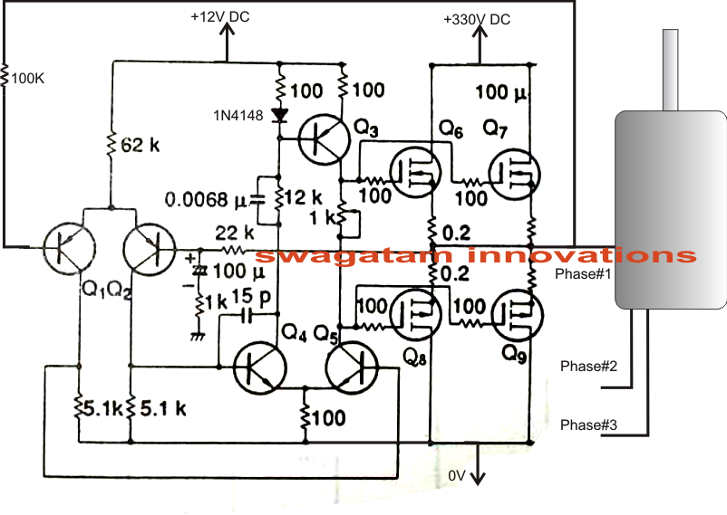
Single Phase AC to Three Phase AC Converter Circuit

IGBT Module, IGBT Power Module Distributor -Rantle

simulation - How to set phase delay for a three phase igbt rectifier

IGBT drive circuit with discrete component - Control_Circuit - Circuit